Evaluation of feeders and feeder materials
The evaluation of feeders is an essential factor in guaranteeing high-quality cast components.
Feeders are designed to prevent the volume loss as castings cool and shrink. Foundries expect feeders to perform reliably and consistently – in accordance with manufacturers’ specifications. There are currently three specifications published by the Federal Association of German Foundry Industry (BDG) for evaluating feeders. For insulating and exothermic feeders, Specification P82 “Evaluating the effectiveness of feeders in steel casting" and Specification P83 “Evaluating the effectiveness of feeders in iron casting” apply. A third specification, P81, specifies procedures for “Evaluating exothermic materials”.
Summary
The first stage in evaluating the properties of feeders involves conducting casting tests at Chemex Foundry Solutions GmbH R&D. This preliminary screening is followed by module tests to obtain further data for the development of new feeder formulations. After a feeder material has been developed, the tests are carried out in accordance with BDG Specification P81. When comparing the characteristics of the Chemex test procedure with those of the P81 test procedure, there is no correlation between burning and casting behaviour. Chemex Foundry Solutions is working together with other feeder manufacturers to develop an improved testing procedure for feeders, which could also be used by customers.
Test according to P81
Specification P81 lays down procedures for evaluating the uniformity of the thermal properties of exothermic feeder materials, i.e. the formulation is checked by the manufacturer. The operating principle of the exothermic feeder, on the other hand, is defined by the casting and described in Specifications P82 and P83. Casting exothermic feeders on cubes or plates allows the module to be evaluated, the details of which are then published in the feeder manufacturers’ catalogues.
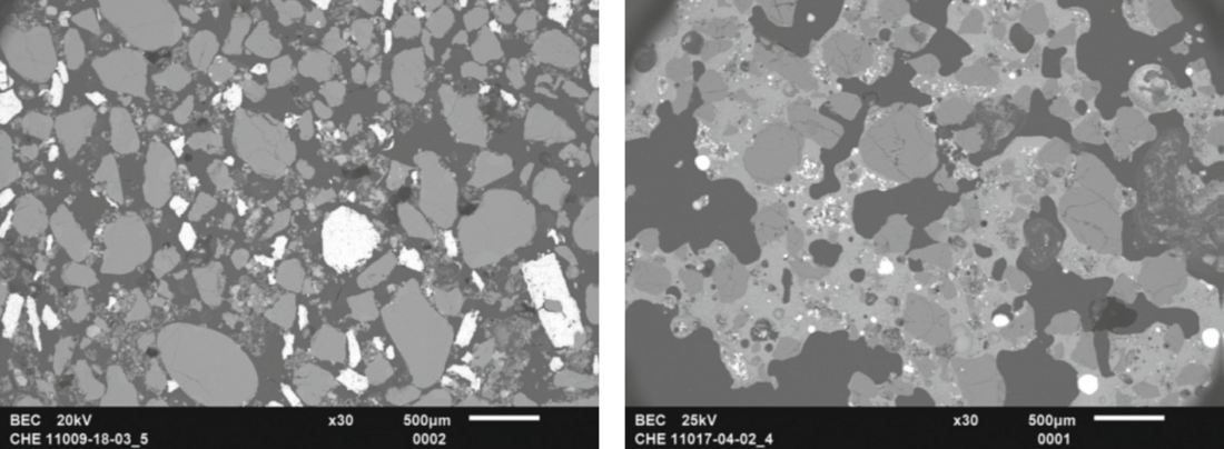
It is often generally assumed that Specification P81 can also be used to assess the performance of exothermic feeders, assuming a correlation between burning behaviour and feeder performance. However, atmospheric oxygen is also used for the reaction of the feeder material during burning, whereas during casting in a fully moulded system only the oxygen present in the formulation is available and these oxygen compounds first have to be broken down. As a result, burning behaviour and casting behaviour are two different reaction mechanisms which do not correlate. This is clear under the scanning electron microscope (SEM) (Fig. 1).
For this reason, manufacturers use casting and corresponding module tests to develop their feeder formulations. It is only after this that manufacturers determine the ignition, burning and heating times as a temperature-time curve for the production test of the masses according to P81.
This test is performed with cylindrical standard test bodies. During the test, ignition, burning and heating times as well as the maximum temperature are determined by measuring the temperature inside the test body over time. The position of the thermocouple is standardised. What does vary are the type of the thermocouple and the properties of the protective tube which sheaths the thermocouple. These are the data which influence the results and are indicated accordingly in the test reports. The use of heating plates is recommended as a medium for ignition of the exothermic feeder materials, but ignition cylinders of a defined composition can also be used. The method used to ignite the test bodies has been a source of justified contention.
The mode of operation of exothermic feeders is based on the Goldschmidt reaction: 2Al + Fe2O3 → Al2O3 + 2 Fe (metal + metal oxide → metal oxide + metal)
This is an exothermic reaction that achieves high temperatures. Triggering the reaction requires activation energy. During casting, the exothermic feeders are ignited by the casting metal. In order to reduce the amount of activation energy required, ignition and other oxidising agents are added to the feeder formulation. One of the aims of developing an exothermic feeder compound is to ensure reliable ignition of the reaction during casting. Burning off the feeder material in accordance with the P81 Specification requires a correspondingly large amount of activation energy, which is achieved by heating the material to ignition temperature. In some cases, this is not always reliably ensured when using heating plates, especially with low-fluorine and fluorine-free feeder materials. Therefore, the development of alternative ignition devices would certainly be welcomed.
New feeder formulations
Chemex Foundry Solutions GmbH is dedicated to developing new state-of-the-art feeder formulations. For health and environmental reasons, it is important to increasingly avoid fluorine-containing active ingredients and to control the reaction mechanisms by means of more suitable ignition and oxidising agents (see also Chemex patents DE0104289 and DE102012213840). The performance of the exothermic feeder is also controlled by the use of high-performance refractory fillers, which enable a good heat balance and thus good insulating properties to be achieved (see also Chemex patents DE102007012660, DE102011079692, DE102011079692, DE102015120866, DE102016205960).
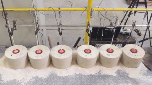
For the development of the formulations, numerous casting tests are carried out. One of the first tests is the casting test according to P14–84 (internal nomenclature). Here, feeders of a defined geometry, coated in a sand mould, are cast with a defined iron melt. The temperature within the melt is measured over time. Pt/Rh-Pt thermocouples, clad with quartz glass tubes of defined dimensions, are used for this purpose. This method also uses a defined thermocouple position. The casting test applies a three-fold determination. The feeders are cast with the opening facing upwards. A substantial volume of heat energy is radiated from the opening, but this is tolerated because this test setup allows the ignition and the combustion process within the feeder wall to be observed (Fig. 2).
The Chemex proprietary P14–84 method is used to determine the parameters relevant for the effectiveness, such as Tmax, holding time and liquidus-solidus transition. A further advantage of the method is that is also allows an evaluation of insulating feeder performance. In accordance with the evaluation of the temperature-time curves determined as per P14–84, module tests follow in the next optimisation phase of the formulations. Compared to the natural feeder, the feed and shrink hole pattern of the sawn cubes or cuboids provides information about the module extension factor and thus the feeding reliability. In both P14–84 and the module tests, the feeders are evaluated after casting with regard to their reaction mechanisms and the quality of the reaction, based on numerous tests including SEM/EDX tests of the feeders.
Test results
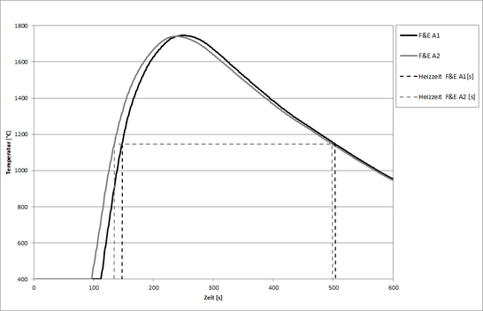
The following section presents selected results of an exothermic feeder formulation tested according to the procedure described above. Figure 3 shows the “burning curves” according to P81 of an exothermic feeder material, marked with “A” as double determination. These are laboratory samples produced and tested in R&D. The temperature is measured over time with thermocouples of type B, Pt30% Rh/Pt6 %Rh (accuracy Class 3 ±4.0 °C or ±0.005 |t|). The thermocouples are sheathed in ceramic protection tubes (610 Pythagoras) with a defined inner and outer diameter to prevent damage to the thermocouples.
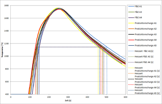
Figure 4 shows the temperature-time curves of three R&D samples and five samples from the running production of the exothermic feeder material “A”. For a better overview, individual measurements are shown in each case.
Table 1 summarises the essential characteristics of the feeder material “A”. A comparison of the production and laboratory data reveals a positive correlation. Methodological errors include measurement errors caused by the measurement variations of the thermocouples, the compensating cables between thermocouple and data logger and the errors caused by the sheathing with the ceramic protection tube. These errors can be minimised by selecting suitable thermocouples, taking into account application temperatures and accuracy classes. In addition, the measurement setup, i.e. thermocouple, compensating cable and data logger, can be calibrated accordingly. Larger errors are due to how the method itself is carried out, e.g. by the use of unsuitable thermocouples, unsuitable or unevenly formed protection tubes and uneven drilling of the holes for the thermocouples.
Table 1: Test results for an exothermic formulation, data from three R&D samples and five production batches of feeder formulation “A”.
| Mix/Charge | Ignition time [s] | Burning time [s] | Heating time [s] | Tmax. [°C] |
| R&D A1 | 6 | 197 | 356 | 1746 |
| R&D A3 | 7 | 186 | 346 | 1752 |
| R&D A4 | 8 | 185 | 338 | 1755 |
| Production Batch A1 | 7 | 163 | 328 | 1761 |
| Production Batch A2 | 10 | 186 | 340 | 1756 |
| Production Batch A3 | 8 | 186 | 343 | 1757 |
| Production Batch A4 | 8 | 182 | 342 | 1739 |
| Production Batch A5 | 8 | 183 | 323 | 1757 |
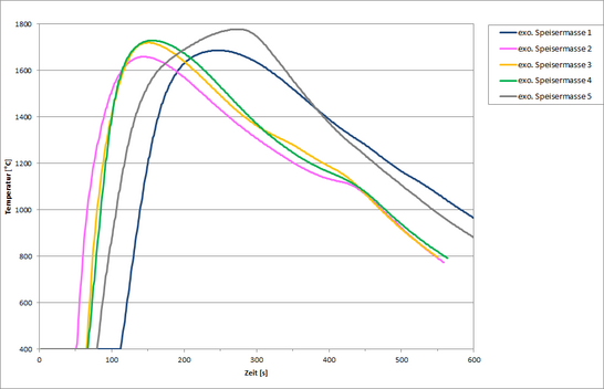
Using this method, the temperature-time curves of each exothermic feeder material are determined (Figure 5). The ignition and firing time parameters serve as set values for control of the running production, while other data are used to check the reference samples in the event of complaints.
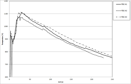
Having tested the burn-off behaviour of organically bound feeders in accordance with BDG Specification P81 by means of infrared and/or pyrometer measurement using equipment from various manufacturers, Chemex decided not to continue such testing. This method records the infrared radiation emitted by the test body. The emissivity depends on the material, the surface condition, the temperature, the wavelength and the measurement setup. Refractory fillers have different emissivity values than metals. Since pyrometer measurements are point measurements of a few millimetres in diameter on the surface (usually 1 to 3mm are recommended by the manufacturers) and the raw materials within the feeders, both non-metals and metals, are usually in the grain size range of 0 to 1mm, the measurement result varies within an unacceptable range depending on which grains are detected during combustion. The possible smoke development depending on the binder system used can also negatively influence the measurement results. Figure 6 shows R&D samples of feeder material “A” as a three-fold determination. The measurement differences for a multiple determination are not acceptable.
Testing according to Chemex casting method
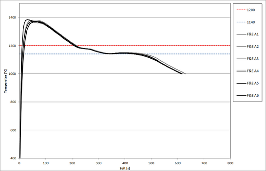
The Chemex casting method P14–84 for formulation development described above also leads to the recording of temperature-time curves. The measurements were made with type B thermocouples, Pt 30% Rh / Pt 6% Rh (accuracy Class 3 ±4.0°C or ±0.005|t|). The thermocouples are sheathed with quartz glass tubes with defined inner and outer diameters. EK 40/70 is used as the feeder geometry to be tested. Performance-relevant characteristics obtained from these curves include Tmax and the time to 1200°C and 1140°C. Since the measurement is carried out with open feeders, the parameters are not comparable with a foundry casting system. However, the method does allow the formulations to be compared in order to gain a first evaluation of the feeding performance. Fig. 7 shows the temperature-time curves recorded during casting according to method P14–84. These are two R&D batches, each of which was tested as a three-fold determination on two different casting days. Table 2 displays the key data determined from the curve progressions.
Table 2: Test results for exothermic feeders from R&D laboratory samples of feeder formulation “A”.
| Tmax. [°C] | t to1200 °C [s] | t to 1140 °C [s] | |
| R&D Sample A1 | 1381 | 216 | 474 |
| R&D Sample A2 | 1369 | 210 | 446 |
| R&D Sample A3 | 1376 | 207 | 462 |
| R&D Sample A4 | 1374 | 212 | 434 |
| R&D Sample A5 | 1384 | 206 | 453 |
| R&D Sample A6 | 1371 | 207 | 452 |
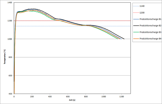
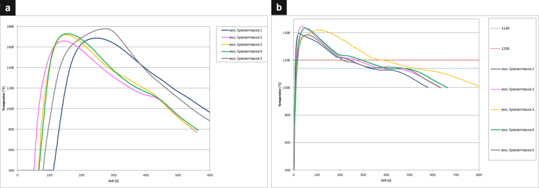
Figure 8 shows the temperature-time curves of four production batches of feeder “B”. The geometry tested was EKD 70T, not EK 40/70.
The four production batches deliver comparable feeding performance within the margin of error. This can also be seen from the key data in Table 3. Measurement errors caused by the measuring inaccuracies of the thermocouples, by the compensation cables between thermocouple and data logger as well as by the protection tube, are also smaller with this method than any errors caused by systematic methodological errors. A majority of errors relate to casting temperature and the feeder filling.
Table 3: Test results for exothermic feeders from four production batches of feeder formulation “B”.
| Tmax. [°C] | t to 1200 °C [s] | t to1140 °C [s] | |
| Production batch 1 | 1326 | 462 | 903 |
| Production batch 2 | 1330 | 480 | 933 |
| Production batch 3 | 1310 | 513 | 854 |
| Production batch 4 | 1314 | 520 | 864 |
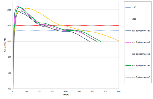
Measurement errors caused by the measuring inaccuracies of the thermocouples, by the compensation cables between thermocouple and data logger as well as by the protection tube, are also smaller with this method than any errors caused by systematic methodological errors. A majority of errors relate to casting temperature and the feeder filling. Figure 9 shows the temperature-time curves of various exothermic standard feeders, determined according to the proprietary Chemex casting method P14–84 to evaluate the feeder performance characteristics.
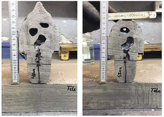
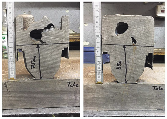
The comparative testing of the blowhole behaviour on module cubes or plates is still the most illustrative but also the most complex test, since in addition to producing the box and mould, saw cuts are also necessary. The feeding module is determined by the geometry of the feeder and by the feeder formulation. Test castings can be conducted to evaluate both the new feeder and a natural feeder, thereby allowing the module extension factor to be determined in comparison to the natural feeder (see P82 and P83). For casting tests within the R&D department, cube tests are carried out with a standardised feeder geometry, mould production and melt (EN-GJS-400-15).
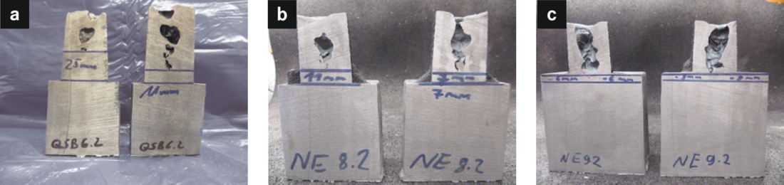
Figure 10 depicts the results of the exothermic feeder material “A” in comparison to the natural feeder. The images reveal that the exothermic feeder “A” has a module extension factor of 1.4 to 1.6.
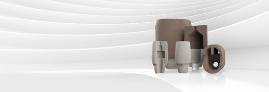
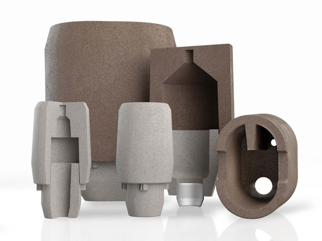
In addition to simple cube and/or plate trials in R&D to determine the characteristics of the feeder formulations, casting is also carried out using different feeder geometries and formulations, e.g. as tele-feeders for comprehensive customer consulting (Fig. 11).
Conclusion
This research confirms that a variety of tests are required to evaluate feeder-relevant characteristics and to ensure reliable and efficient feeder performance for customers. The development of new feeder materials primarily focusses on casting tests on plates or cubes, followed by in-foundry casting tests to ensure optimum adaptation to the casting parameters during customer use. For initial measurements of the feeder properties, Chemex carries out internal R&D casting tests according to P14–84. Only after this pre-screening do we proceed to module tests. This ensures reliable and efficient data acquisition for the development of new feeder formulations. Testing not only determines the performance of the exothermal systems but also the performance of the refractory fillers to optimise the insulation behaviour of feeder materials. Only after these tests have been concluded is the new feeder material tested according to P81 to document the ignition, burning and heating times for production control and testing in case of complaints.
As can be seen in Figure 13, the characteristics of the test methods P81 and P14–84 differ significantly, since no correlation between burning and casting behaviour is exhibited. Therefore, the test according to P81 is only suitable for testing exothermic masses, but not for testing the performance of exothermic feeders. For this reason Chemex, together with other manufacturers, is working on the development of an improved test method for feeders, which could also be used by customers.
The scope of the production evaluation of the feeders and feeder materials is largely determined by upstream quality measures, such as R&D work during formulation development, specifications of the raw materials used and incoming goods inspections, as well as the production parameters. In addition to the production of fluorine-free feeder formulations, Chemex is also focused on developing new and innovative refractory fillers to ensure optimum feeder quality.
Authors: Sandra Lehmann, R&D Senior Manager Feeding Systems, Hüttenes-Albertus Chemische Werke GmbH, Hannover; Heiko Schirmer, Betriebsleiter, Chemex Foundry Solutions GmbH, Delligsen; Sven Dommen, Produktmanager, Chemex Foundry Solutions GmbH, Düsseldorf
Published: September 2020